The
Page Format Designer function lets the user
create new drawing page formats or modify existing formats. It can also extract
page formats from project files received from someone else.
Accessed from:
The dialog consists of six step options which are listed
on the left side. Each step provides a different list of settings fields in
which to define/modify the page format.
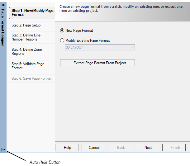
Step 1: New/Modify
Page Format
Select from one of the options detailed in the table
below to begin the designing process.
Note: There is an
Auto Hide button in the lower left corner of the
dialog that sets whether or not the settings area will be hidden if you move
the cursor back to the drawing area (so it is not in the way). If auto hide is
turned on, you can click on the desired step button to display the setting area
again.
| Setting | Description |
|---|
| New Page Format
|
Creates a new page format from scratch.
|
| Modify Existing Page Format
|
Edits a page format that already exists.
|
| Extract Page Format From Project
|
Allows you to extract an existing page format from
a project. The following dialog displays:
- Select the desired
project in the
Project field. The page formats in
that project will then be listed.
- Select the page
format you wish to extract. You can give the format a different name in the
Save as field, if desired.
- Select
OK to extract the page format and save
it in your page format folder.
|
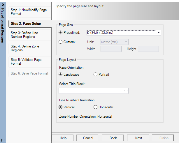
Step 2: Page
Setup
In Step 2 of the Page Format Designer , you set the
dimensions and orientation of the page format.
| Setting | Description |
|---|
| Page Size
|
Predefined: Select one of
the existing ANSI or IEC page sizes.
Custom: Select metric or
inch units and enter values in the Width and Height fields.
|
| Page Orientation
|
Select either Portrait or Landscape.
|
| Select Title Block
|
Use the
Browse button to select one of the
existing title block macros to use as a reference.
This title block appears on the screen while you are
creating the page format but is not stored with it (you can select a different
title block when using the format to create drawing pages).
|
| Line Number Orientation
|
Vertical: Line numbers will appear going
down the page.
Horizontal: Line numbers will appear
going across the page.
|
| Zone Number Orientation
|
This setting will be automatically set to the
opposite of the line number orientation.
|
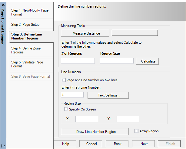
Step 3: Define Line
Number Regions
Step 3 of the
Page Format Designer defines the line number
regions. A line number region is the area of a page assigned to an individual
line number. (At this point a representation of the page format will appear in
the drawing area.)
Define the options detailed in the table below to specify
the line number regions.
| Setting | Description |
|---|
| Measuring Tools
|
The
Measuring Tools area of the dialog is a
utility that helps you to calculate the region size you will enter in the lower
part of the dialog.
- Measure Distance: You will be taken to the drawing area
where you can click on a first point and a second point to define where the
first and last line numbers will appear. The distance between the two points
that you selected will be entered automatically in the field beside the Measure
Distance button.
- #
of Regions/Region Size: Enter a value in either of these fields. (For
example: if you wish the line numbers to be 0.5 inches apart, enter 0.5 in the
Region Size field). Then select Calculate to automatically calculate the
appropriate value for the empty field.
Note: The values you
calculate in the
Measuring Tools area are not used
automatically - they are only intended to help you determine what settings to
use when drawing the region.
|
| Line Numbers
|
In
Line Numbers area of the dialog, you
make the actual settings that will be used in your page format.
If you wish the page number to appear on a separate
line, select the
Page and Line Number on Two Lines check
box. (To determine whether or not a page number is included with the line
number, use the
Include Page Number as a Line Number
Prefix check box in the Default Page Properties dialog.
In the
Enter (First) Line Number field, enter
a value for the line number of the region you are drawing. If you are using the
array function (see below) enter the first line number.
Use the
Text Settings button to make text
settings for the line numbers. The
Edit Text Format dialog will appear.
This dialog is similar to the
Edit Text Style dialog . One important
difference is the
Text Align field which allows you to set
in which direction the data will be placed from the variable's insertion point.
Select
OK when the desired settings are made.
|
| Region Size
|
Use the
Region Size section to draw each line
number region:
To Draw a Line Number Region:
- Select your drawing
method: you can either define an area on the screen (select the
Specify on Screen check box) or enter X
and Y values in the appropriate fields to set the size of the region.
- Select the
Draw Line Number Region button. You will
be taken to the drawing area where you will either define a box for the region
or place the box that was defined by the X and Y values.
- After drawing or
placing the region you will be prompted on the command line to pick the line
number text position. Click on the desired position for the line number. The
line number must be placed inside the boundary of the region.
- To return to the
Page Format Designer after you draw a region you can press the
<Esc> or
<Enter> keys or click the right
mouse button. Line number regions appear in the drawing area as green boxes.
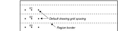
Note: While drawing
the regions, you will probably need to use a smaller grid so that the region
borders can fall between your default drawing grid spacing.
Delete Region: To delete a region you
have placed, click on the region so that it has a dotted border and then press
the <Delete> key.
Copy Region: You can copy regions that
you have placed using the standard copy function. You will have to edit the
number text of the copy so that it is different from the original.
|
| Array Region
|
To draw a series of regions in one step:
- Select the
Array Region check box.
- Enter a value for
the first line number in the
Enter (First) Line Number field.
- Select the
Draw Line Number Region button.
- Draw or place the
first region and select the text position for that region.
- You will be prompted
to "pick the last position of the array region." Click the point where you wish
the last region to end. The software will draw as many regions as it can fit
between the first region and the selected point.
|
Step 4: Define Zone
Regions
In Step 4 of the Page Format Designer, you can define zone
regions. A zone region is the area of a page assigned to an individual zone.
Define the options detailed in the table below to specify
the zone number regions.
| Setting | Description |
|---|
| Measuring Tools
|
The
Measuring Tools area of the dialog is a
utility that helps you to calculate the region size you will enter in the lower
part of the dialog
- Measure Distance: You will be taken to the drawing area
where you can click on a first point and a second point to define the area of
the drawing that will be occupied by zones. The distance between the two points
that you selected will be entered automatically in the field beside the Measure
Distance button.
- #
of Regions/Region Size: Enter a value in either of these fields. (For
example: if you wish the line numbers to be 0.5 inches apart, enter 0.5 in the
Region Size field). Then select Calculate to automatically calculate the
appropriate value for the empty field.
|
| Zone Numbers
|
In the Zone Numbers area of the dialog, you make
the actual settings that will be used in your page format.
-
Enter (First) Zone Number: Enter a
number for the zone that you are drawing. If you are using the array function
(see below) enter the first zone number.
- Text Settings: Click to make text settings for the zone
numbers. The
Edit Text Format dialog will appear.
This dialog is similar to the
Edit Text Style dialog. One important
difference is the Text Align field which allows you to set in which direction
the data will be placed from the variable's insertion point.
Select
OK when the desired settings are made.
|
| Region Size
|
Use the
Region Size section to draw each line
number region:
To Draw a Zone Region:
- Select your drawing
method: you can either define an area on the screen (select the
Specify on Screen check box) or enter X
and Y values in the appropriate fields to set the size of the region.
- Select the
Draw Zone Region button. You will be
taken to the drawing area where you will either define a box for the region or
place the box that was defined by the X and Y values.
- After drawing or
placing the region you will be prompted on the command line to "pick the text
position." Click on the desired position for the zone number. The zone number
must be placed inside the boundary of the region.
- To return to the
Page Format Designer after you draw a region you can press the
<Esc> or
<Enter> keys or click the right
mouse button. Zone regions appear in the drawing area as green boxes.
Note: While drawing
the regions, you will probably need to use a smaller grid so that the region
borders can fall between your default drawing grid spacing.
Delete Region: To delete a region you
have placed, click on the region so that it has a dotted border and then press
the <Delete> key.
Copy Region: You can copy regions that
you have placed using the standard copy function. You will have to edit the
number text of the copy so that it is different from the original.
|
| Array Region
|
To draw a series of regions in one step:
- Select the
Array Region check box.
- Enter a value for
the first zone in the
Enter (First) Zone Number field.
- Select the
Draw Zone Region button.
- Draw or place the
first region and select the text position for that region.
- You will be prompted
to "pick the last position of the array region." Click the point where you wish
the last region to end. The software will draw as many regions as it can fit
between the first region and the selected point.
|
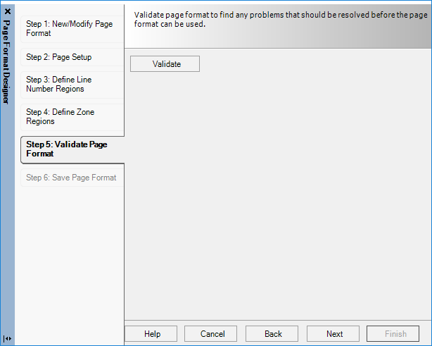
Step 5: Validate
Page Format
In Step 5 of the
Page Format Designer, you let the software
check your format for possible problems.
Select the
Validate button. If no problems are encountered,
the following message will be displayed.
If errors are encountered, you can click on the error and
the software will navigate to and display the problem area. The software checks
for the following conditions:
-
Overlapping line number regions: The software
cannot function properly if this condition exists.
-
Overlapping zone number regions: The software
cannot function properly if this condition exists.
-
Gaps between line number regions: (The
software may not properly calculate the correct line number of a device placed
in such a gap.)
-
Gaps between zone regions: (The software may
not properly calculate the correct zone number of a device placed in such a
gap.)
-
Line number region without a line number text:
Each line number region must have at least one line number text within its
boundary. The software cannot function properly if this condition exists.
(There can be more than one line number text within a region but these texts
must have the same value.)
-
Zone number region without a zone number text:
Every zone region must have at least one zone number text within its boundary.
The software cannot function properly if this condition exists. (There can be
more than one zone number text within a region but these texts must have the
same value.)
- Line numbers
and zone numbers outside of a region: The software cannot function
properly if this condition exists. Each line or zone number must exist within
the boundaries of a region.
-
Duplicated line or zone numbers in different
regions: (This may or may not be a problem since you may intend to
do this in certain page formats.)
- Staggered line
number regions: a line number region that spans across two other
line number regions: The software cannot function properly if this condition
exists.
-
Staggered zone regions: a zone region that
spans across two other zone regions: The software cannot function properly if
this condition exists.
Note: You can still
proceed to the next step and save the format without correcting these
conditions, but some of the conditions may prevent the format from working
correctly or cause an error message when you attempt to use it.
Save Page
Format
The final step of the Page Format Designer process is to
save the completed page format.
Enter a
Format Name and
Description for the format in the appropriate
fields then select
Finish to save the format.
Note: The format is saved
in the PageFormat folder of your
OpenUtilities Substation
installation.